This page contains information for better understanding how the deepfifo module works. For downloading and using deepfifo, please refer to this page.
Principle of operation
As shown in the diagram below, the solution consists of the following elements:
- The deepfifo Verilog module
- The “Pre FIFO”, which is a standard dual-clock FPGA FIFO. This FIFO is connected between the data source and the deepfifo module.
- The “post FIFO”, which is also a standard dual-clock FPGA FIFO, connected between the deepfifo module and the data sink.
- An AXI slave, which exposes a memory.
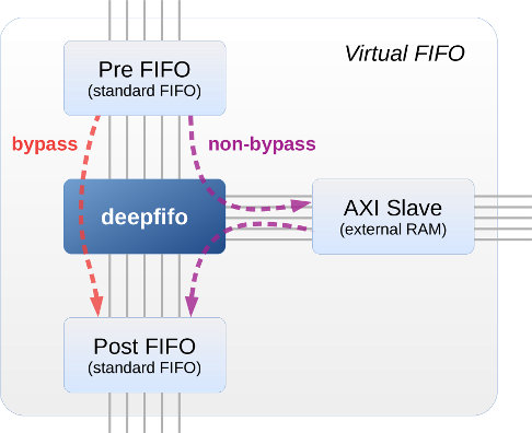
The deepfifo module is always in one of two modes:
- Bypass mode: In this mode, the Pre FIFO and Post FIFO behave like one FIFO with double depth. The module simply moves data directly from the Pre FIFO to the Post FIFO. More precisely, for each rising edge of the AXI bus clock, one data element is read from the Pre FIFO and written to the Post FIFO, unless the Pre FIFO is empty and/or the Post FIFO is full.
- Non-bypass mode: Bursts of data from the Pre FIFO are moved into the AXI slave, and likewise data from the AXI slave is moved to the Post FIFO.
The module starts at bypass mode after reset. It goes into non-bypass mode when the number of elements in the Pre FIFO goes above a threshold level, which is an indirect result of the Post FIFO being full while data arrived from the data source.
Going into non-bypass mode, data from the Pre FIFO being moved into the RAM, and data is moved from the RAM into the Post FIFO whenever there’s room for it. As the data transfers with the RAM take place in bursts, data is moved in non-bypass mode only when a full burst can take place.
It’s possible for the RAM to be completely filled with data, in which case the Pre FIFO will not be drained, and it may become full. This mimics the behavior of a standard FIFO.
The module returns to bypass mode when the RAM contains no data (all data has been delivered to the Post FIFO) and the Pre FIFO’s number of elements is below the same threshold level. This mimics the behavior of a standard FIFO for data segments smaller than an AXI burst, in particular as the virtual FIFO becomes empty.
Design principles
The main goal of deepfifo’s design is not to push your luck with the AXI slave it works with. Accordingly:
- Read / write bursts are issued with a constant length, hence avoiding corner cases related to crossing alignment boundaries and less commonly used burst lengths.
- Once a burst has been requested, the data flow is never throttled by this module: The RREADY and WVALID signals are held asserted as long as there are outstanding bursts in the relevant direction. Some AXI slaves don’t allow data throttling at all, and others may expose corner-case bugs when throttled with unfortunate timing.
- The AXI slave’s RLAST signal is used for keeping track of arriving bursts. The number of words that arrived aren’t counted — it’s assumed that the slave sent the number requested.
- The write response channels (BVALID/BREADY) are used as an indication that the write has been completed, in the sense that a read request from the same address yields correct data. This is based upon the AXI standard.
- The controller assumes that read and write AXI bursts transactions are successful, and ignores the status signals BRESP and RRESP (which might indicate an error if such has occurred)
Implementation details
The overall approach of this module’s design is to maintain the count of certain quantities, and make decisions based upon their values. This is the list of the relevant registers and their meaning. With these understood, reading the module’s Verilog code should be fairly straightforward.
- bursts_allocated: Number of non-free burst-size data segments in RAM. Used for preventing a RAM write bursts that would overwrite existing valid data (i.e. telling that the virtual FIFO is full) and for allowing the return to bypass mode. Incremented when the AXI write command is issued, decremented when an AXI read burst cycle is completed (all data has arrived).
- bursts_stored: Number of burst-size data segments containing valid data that is available for reading. Used solely for preventing a RAM read bursts when there’s no valid data in the RAM at all (i.e. the virtual FIFO is empty, in which case bursts_stored == 0). Incremented when the AXI write command is completed, decremented when an AXI read burst cycle is issued.
- min_pre_rd_count: The minimal required number of words stored in the pre-FIFO in order to issue a write RAM burst request (which will drain data from this FIFO). Discussed further below.
- max_post_wr_count: The maximal number of words already stored in the post-FIFO in order to issue a read RAM burst request (which will push data to this FIFO). Discussed further below.
- beats_to_ram_left: Number of word transfers (beats) related to write bursts that are left, for the purpose of keeping the AXI WVALID signal asserted. Decremented by one for each word transfer. For each write burst request issued, the number of words in a burst is added to this register.
- bursts_from_ram_left: Number of uncompleted read bursts, for the purpose of keeping the AXI RREADY signal asserted. Decremented by one for each word that arrives from the AXI slave with the AXI RLAST signal asserted. Incremented by one for each issued read burst request.
- wburst_count: Keeps track of the position of each word in a write RAM burst for the sake of asserting the AXI WLAST signal at the end of each burst boundary.
- to_ram_burst_pos, from_ram_burst_pos: These two counters maintain the write and read address position respectively in the RAM, in burst size quanta. These are used to tell when to wind back to the lowest address after a AXI burst request has been issued.
Some decision rules
Non-bypass mode is started when the Pre FIFO is filled beyond its threshold, i.e. fifo_pre_rd >= fifo_threshold.
Going back to bypass mode: When the Pre FIFO is filled below its threshold, the RAM contains no data, no write burst is initiated and won’t be initiated on this clock, i.e. when these conditions are met:
- fifo_pre_rd < fifo_threshold
- bursts_allocated == 0 (recall that burst_allocated is incremented when a burst request is issued)
- do_to_ram_burst is not asserted, hence no burst request is about to happen on this clock
- axi_awvalid == 0 (don’t issue a request if one is pending)
- bypass_mode == 0
- fifo_pre_rd_count >= min_pre_rd_count.
- bursts_allocated < bursts_in_ram (the latter is calculated from the log2_bursts_in_ram parameter)
Rules for allowing the request of a RAM read burst: Must be in non-bypass mode, there must be enough room in the post FIFO and at least one burst ready for reading in the RAM. Formally,
- axi_arvalid == 0 (don’t issue a request if one is pending)
- bypass_mode == 0
- fifo_post_wr_count <= max_post_wr_count (max_post_wr_count’s MSb is treated as a sign bit, so max_post_wr_count may be considered negative in this inequality)
- bursts_stored != 0
min_pre_rd_count and max_post_wr_count
In order to maintain a continuous data flow, read and write bursts requests must be issued in advance. In order to allow the maximal possible pending burst requests, the deepfifo module performs bookkeeping on how much data can be transmitted from or to the relevant FIFO, before it underflows or overflows, respectively.
For the RAM write direction, the min_pre_rd_count register is at all times the minimal number of words required in the Pre FIFO in order to request a write burst from the AXI slave (which results in data drained from this FIFO). It’s initialized to the number of words in a burst plus 8, so the FIFO must contain at least enough data for a single burst (plus 8 words) for the first burst request to be issued.
When a RAM write burst request is issued, the number of words in a burst is added to min_pre_rd_count, to reflect the fact this number of words has already been promised to the AXI slave. For each word that is transmitted to the AXI slave from this FIFO, this register is incremented by one, as there’s one less word yet to be transmitted.
Accordingly, one of the requirements for issuing a RAM write burst is that the number of words in the Pre FIFO, as reported by the FIFO through its rd_data_count port, is larger or equal to min_pre_rd_count.
Note that min_pre_rd_count can exceed the number of words totally available in the Pre FIFO, for example if the FIFO is full and burst requests have been issued on behalf of all its data.
The max_post_wr_count register is used for RAM read bursts a similar way: It maintains the maximal number of words that the Post FIFO may contain in order to issue a read RAM burst (which results in data filling this FIFO). It’s initialized to the number of words possible in the FIFO minus the number of words in a burst, minus 8. The FIFO must hence have room for data from a single burst (plus 8 words) as a condition for issuing a RAM read burst.
When a RAM read burst request is issued, the number of words in a burst is reduced from max_post_wr_count, to reflect the fact this number of words’ worth of space has already been promised to the AXI slave. For each word that is transmitted from the slave to this FIFO, this register is decremented by one, as there’s one less word yet to be transmitted.
Accordingly, one of the requirements for issuing a RAM read burst is that the number of words in the Post FIFO, as reported by the FIFO through its wr_data_count port, is smaller or equal to max_post_wr_count.
Note that max_post_wr_count can become negative, for example if the Post FIFO is empty and burst requests have been issued on behalf of all data it can take. As Verilog signed semantics isn’t used in deepfifo (once again, don’t push your luck), an extra bit is allocated to max_post_wr_count as a sign bit. No burst request is issued if this bit is ‘1′, as it essentially means that the FIFO is required to contain a negative number of words.
Still left to explain is why the number of 8 was added or subtracted from the initial values of these two registers. The reason is that the FIFOs’ word counters (rd_data_count and wr_data_count) always have a latency (typically one extra clock). In addition, the actual maximal number of words that a FIFO can occupy is one less than the said radix-2 number for Xilinx’ dual-clock FIFOs (e.g. 511 words on a “512 words FIFO”).
Even though it would be enough to add 1 to min_pre_rd_count and reduce 2 from max_post_wr_count to overcome this issue on a Kintex-7 (this is both theoretically correct and has been verified on hardware), the number 8 has been chosen as an overkill precaution for whatever additional inaccuracies that may arise on other environments. It also allows using FIFO wrappers for improved timing without the need to adjust the FIFO’s data counters.