Introduction
A Xillyp2p IP core consists of two netlists, referred to as Core A and Core B. Each of these two netlists is intended for instantiation in one of the two FPGA projects involved in setting up the data link.
The ports of Core A and Core B are usually not identical, as the physical link isn't necessarily symmetric, and neither are the application data streams in most cases. That said, the structure of these ports is the same for both cores.
The ports can be divided into four groups:
- Ports to be connected with the MGT, SERDES or other physical link. These consists of the parallel word and the clock related to it. There can also be an optional input port for throttling the data flow with the physical link.
- Ports used to communicate application data. These are connected to standard FIFOs that are instantiated by the core's user.
- The reset port.
- Ports used for status, testing and troubleshooting.
This is a slightly simplified diagram showing how the Xilltp2p IP core is connected in a design involving an MGT or SERDES:
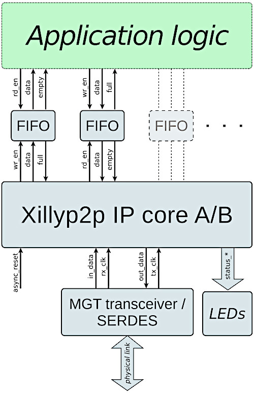
A few of Xillyp2p IP core's ports are omitted in the diagram for the sake of clarity. These ports are nevertheless described below, with a comment saying that they're missing in the diagram.
Ports connecting with physical link
The following two ports are used to carry the parallel word stream for transmission by the physical link to the other side. They are present on both netlists if the IP core is bidirectional, or only on core A for unidirectional cores.
- out_data (output): This bit vector output contains the parallel data that the physical link transmits to the other side. The bits are transmitted starting from bit 0 and ending at this word's most significant bit. The width of this output word is configured in the IP Core Factory to any number between 1 and 128.
- tx_clk (input): The clock used with out_data. In fact, all other ports are clocked with this clock, except for in_data and in_valid, when these two ports are present.
If the physical link is unidirectional, neither of these two ports are present on core B, and all ports are clocked with rx_clk mentioned just below.
These two following ports are used to carry the parallel word stream that is received from the other side through the physical link. They are present on both netlists if the IP core is bidirectional, or only on core B for bidirectional cores.
- in_data (input): This vector input contains the parallel data that arrives from the physical link. The bits are ordered starting from bit 0 and ending at this word's most significant bit (in the same way as out_data). The width of this output word is configured in the IP Core Factory to any number between 1 and 128.
- rx_clk (input): The clock used with in_data. This clock is also used with all other ports if tx_clk doesn't exist, i.e. for core B with a unidirectional physical link (in which case data only arrives, so there's no transmission clock). When an MGT is used as the physical link, rx_clk is the clock derived from the data stream by the MGT itself, by virtue of clock recovery.
When the link is bidirectional, the frequencies of tx_clk and rx_clk must be approximately the same, within a tolerance that is defined when the IP core is configured at the IP Core Factory. These two clocks may also be the same clock signal in some scenarios, or the same clock signal with a different phase.
Note that with a bidirectional physical link, all application data exchange between the application logic and the Xillyp2p IP core is clocked with the transmission clock only. This holds true for application data in both directions. In other words, all application FIFOs are connected to tx_clk (on their half connected to Xillyp2p), even the FIFOs receiving data from the other side.
Throttling the stream parallel word
Within the configuration of a Xillyp2p IP core at the IP Core Factory, there's an option called "A parallel word is transmitted / received on every clock cycle". By default, this option is enabled, which is the correct choice in nearly all cases: An MGT and a SERDES transmits and receives a parallel word every clock cycle.
However, if additional logic is inserted between the Xillyp2p IP core and the physical link, for example a gearbox, it may be required to throttle the flow of parallel words to and/or from the IP core. When this is the case, the option mentioned above should be disabled. By doing so, two ports are added to the netlist:
- out_ready (input, clocked by tx_clk): This input exists if an out_data port exist, and functions as a clock enable for this port. It should be high when the physical link's transmitter is ready to accept the a data word. In other words, the IP core considers the data word in out_data as transmitted when out_ready is high on the same clock cycle.
- in_valid (input, clocked by rx_clk): This input exists if an in_data port exists, and functions as a clock enable for in_data. It should be high when the in_data contains a valid word. In other words, the IP core consumes the data word in in_data when in_valid is high on the same clock cycle.
In summary, throttling is almost never necessary when using an MGT or SERDES, as a parallel word is transmitted and received on every clock cycle. This is why these out_ready and in_valid don't appear in the diagram shown above. However, it's possible to add these two ports when needed.
Reset
The Xillyp2p IP core has one asynchronous reset input, async_reset.
This input should be high until the clock inputs (@tx_clk and/or @rx_clk) are stable with the correct frequency. Even though the reset input is asynchronous, it's recommended to generate this signal as an output of a register, in order to avoid glitches. The reset pulse should be long enough for a flip-flop on the relevant FPGA to respond to an asynchronous reset. For example, one clock cycle of tx_clk or rx_clk is long enough.
It may take a short time for the reset signal to propagate into the IP core's logic. Therefore, data activity may continue for a up to 10 clocks after the reset's assertion. In particular, the IP core may continue to deliver or read data from the application logic during this short time period.
There is no need to use the async_reset after the input clocks are stable. In particular, Xillyp2p supports hotplugging, so if the physical data link is disconnected and connected back, there is no need for a repeated reset, given that the clock inputs remained within their allowed frequency limits.
Status, testing and troubleshooting
The Xillyp2p IP core has several output ports intended for monitoring the physical link's status and quality, as well as the status of Xillyp2p's own protocol. These output ports are described in detail on a separate guide, along with suggestions on how to resolve issues while setting up the physical link.
The Xillyp2p IP core also has a capability of inserting bit errors on the physical link for testing purposes. This allows users to evaluate how their logic copes with the effects of errors on the physical links (i.e. a temporary reduction of the data rate due to retransmission if the link is bidirectional, or the halt/resume mechanism for a unidirectional link).
The error injection mechanism is controlled by the error_test_rate input port (not shown in the diagram above), which is a 3-bit vector. This input should be tied to zero for normal operation.
When this input is non-zero, Xillyp2p's transmitter front-end deliberately and randomly flips the output value of a bit, causing an intentional bit error.
The error rate is estimated as follows: If the number given on error_test_rate is denoted r, the simulated bit error rate (BER) is approximately 10r-10 for r between 1 and 7. For r=0, this feature is disabled and no errors are caused deliberately.
Data exchange with user application logic
Similar to the Xillybus and XillyUSB IP cores, the application data exchange with Xillyp2p takes place through a standard FIFO for each data stream.
For application data for transmission, this means that the application logic writes the data to a FIFO that is instantiated next to the Xillyp2p IP core. The Xillyp2p IP core is connected to the other side of this FIFO. The core reads the data from this FIFO and sends it to the other side.
Note that there is no need to reach a certain amount of data words nor to do anything else in order to initiate the transfer to the other side. To the Xillyp2p IP core, a non-empty FIFO is considered a request to transmit data as soon as possible.
As for receiving application data, this works with a FIFO in the middle as well: The Xillyp2p IP Core writes data a FIFO connected to it, and the application logic reads this data from this FIFO. A flow control mechanism inside the IP core prevents an overflow of the FIFO by respecting its "full" output, which is also connected to the IP core.
However, there are two possible situations where this flow control mechanism isn't available, and there's no possibility to connect the "full" output to the IP core:
- When the link is unidirectional, as there's no way for the receiving side to request a pause in the data flow.
- When flow control is opted out in the stream's configuration at the IP Core Factory (the checkbox next to "Enable flow control with "full" input at receiver" is left unchecked).
In any of these two situations, the application logic must read the application fast enough to prevent the FIFO's overflow.
It's therefore recommended to work with a bidirectional physical link, and enable the flow control mechanism that is based upon the FIFO's "full" port. This creates a true illusion of one FIFO that is split between two FPGAs, and even more importantly, it allows the receiving side to control the flow of data: The application logic on the receiving side reads the data in its desired pace from the FIFO, and Xillyp2p's flow control mechanism ensures that the data flow on the specific stream is temporarily halted when this FIFO on the gets full.
Naming convention of application data ports
As noted earlier, the user is required to instantiate standard FIFOs alongside with the Xillyp2p IP core for the purpose of transmission and reception of application data.
For each application data stream that sends data to the other side, there are three ports connected to the standard FIFO. The IP core uses these ports to read the data for transmission from the FIFO. The names of these ports are
- user_tx_{name}_rd_en, connected to the FIFO's rd_en port.
- user_tx_{name}_rd_data, connected to the FIFO's data output port.
- user_tx_{name}_empty, connected to the FIFO's empty port.
The placeholder "{name}" replaces the stream's name, as given by the user in the IP Core Factory.
Likewise, for each application data stream that receives data from the other side, the IP core uses the following ports to write the data it has received from the other side:
- user_rx_{name}_wr_en, connected to the FIFO's wr_en port.
- user_rx_{name}_wr_data, connected to the FIFO's data input port.
- user_rx_{name}_full, connected to the FIFO's full port. As mentioned above, this port is not present if the physical link is unidirectional or if flow control has been opted out at the IP Core Factory.
When the physical link is unidirectional, each stream that receives data has two additional ports: user_rx_{name}_halt (output) and user_rx_{name}_resume (input). These are explained in further detail below (see "Error handling with a unidirectional physical link").
Important: All application data ports are synchronous with tx_clk, when this clock is present. In other words, every port related to application data – both transmit and receive – is clocked with tx_clk. The only exception occurs with core B in a unidirectional physical link configuration. In that case, rx_clk is used instead, as it is the only available clock source.
End-of-packet (EOP)
As an additional feature, the Xillyp2p IP core allows transmitting an end-of-packet (EOP) flag alongside with each application data word. Note that this isn't required for triggering the transmission of application data to the other side; any data that the user application logic writes to the FIFO is regardless transmitted to the other side as soon as possible.
The only purpose of the end-of-packet flag is as a marker, enabling the user application to divide the data into segments, packets or video frames etc. If the physical link is unidirectional, the EOP flag can be particularly useful (see "Error handling with a unidirectional physical link" below).
If this feature isn't required, tie user_tx_{name}_eop to zero and ignore user_rx_{name}_eop on the receiving side. Although the EOP ports are not shown in the diagram above, they are always included in the IP core's interface.
There is no restriction on how frequenctly the EOP flag is asserted, and hence the segments or packets have no length limits. That said, asserting EOP causes a bandwidth penalty of up to 16 bytes on the physical link. Using EOP to create short packets may hence reduce the bandwidth performance.
The EOP is used as follows: For each data word fetched via user_tx_{name}_rd_data, the application logic provides the corresponding EOP flag through the input port user_tx_{name}_eop. If this input is high along with the data word, that word is marked with the EOP flag.
On the receiving side, the user_rx_{name}_eop output port is high when user_rx_{name}_wr_data contains the word that was sent with the EOP flag set.
Conceptually, the EOP can be viewed an extension of the application data word, making it one bit wider. When EOP is used in an application, it's natural to make the FIFOs' word on both sides one bit wider, and use the extra bit for the EOP flag. In most cases, this won't even increase the FIFO's memory resource consumption.
But once again, the EOP signal is not just another transmitted bit: As long as this bit is '0', no bandwidth is consumed on its behalf on the physical data link. On the other hand, when this bit is '1', there is a slight inefficiency in the use of the physical data link, as mentioned above.
It's not possible to transmit an EOP without an accompanying data word. If that feature is required, the application logic on the receiving side can be designed to ignore the data word when the EOP flag is set.
FIFO depth considerations
It's often desirable to maintain a continuous flow of data between the application logic and its associated FIFO. Given that the stream's allocated data rate allows that, the design question is how deep the FIFO needs to be (i.e. how many data words it needs to be able to store in its memory array).
When transmitting data to the other IP core, the application logic writes data into the FIFO, and the Xillyp2p IP core reads from it. In principle, reading data from the FIFO begins as soon as its "empty" port is low, however this might be delayed because of two reasons:
- The FIFO on the other side is full. This possibility applies only for a bidirectional physical link and when flow control is enabled (recommended).
- The IP core transmits data on behalf of another application data stream.
As for the first possibility, this is related to how rapidly data is consumed on the receiving side. If this is the dominant factor, the FIFOs' depths on both sides should be planned with the same principles as if the two sides of the application were on the same FPGA, connected through a single FIFO.
The second possibility is related to Xillyp2p's data transfer pattern: The IP core checks its user_tx_{name}_empty input ports in a round-robin manner, and initiates a transmission of data for each application data stream that has this signal deasserted. A continuous transmission of slightly less than 1024 bytes takes place, or until the relevant FIFO becomes empty. The IP core then proceeds to the next stream having the "empty" port deasserted (or remains on the same one, if the other FIFOs are empty).
Given this behavior, the FIFO should be deep enough to absorb the data written by the application logic while the IP core is occupied transmitting other streams. A reasonable estimate is to assume that the core transmits up to 1024 bytes per active stream in each round-robin cycle. Thus, the FIFO depth should accommodate the amount of data generated during the time it takes to transmit 1024 bytes for each other active outbound stream.
For this purpose, outbound streams that are known to be idle (in the usage scenario of the stream in question) should not be taken into account, as they don't cause any delay.
As for the FIFOs on the receiving side, data is delivered immediately when "full" goes low, if such is available. In the absence of flow control (i.e. when the link is unidirectional or when the flow control has been opted out), data is delivered as soon as it arrives.
Naturally, the availability of received data depends on whether and how of much of it has been transmitted from the other side. Hence the discussion goes back to the round-robin mechanism already explained above. In other words, the depth of the FIFO on the receiving side should be able to compensate for the gaps in the data flow that occur as other application data streams are serviced, each taking up the physical link for approximately 1024 bytes.
Note that the actual patterns of data delivery may look different from the transmission patterns, as Xillyp2p maintains internal data buffers. The difference is however only in favor of maintaining a continuous data flow, given that the IP core has been configured with the correct parameters at the IP Core Factory.
Error handling with a unidirectional physical link
This section discusses the resumption from an error condition for a unidirectional link, and is hence is irrelevant when the physical links is bidirectional. There is a separate guide about troubleshooting in general.
When the physical link is unidirectional, the transmitting side has no means of knowing whether the data it sends is received correctly. If data is lost due to a bit error or a temporary disconnection of the physical media, the detection of such loss is guaranteed by virtue of a CRC32 check on the application data, as well as a mechanism for detecting gaps between arriving data segments. However, because there is no return channel, the transmitter cannot be informed of the error, nor can it retransmit the affected data.
Xillyp2p ensures that all data delivered to the application logic is error-free and contiguous, exactly as transmitted. Should some kind of error occur on the physical link, Xillyp2p writes as much data as possible to the FIFO, just until before the point the error may have affected the data. After this, the data flow is halted, and the user_rx_{name}_halt output port changes to '1' in order to indicate this.
The data flow resumes to normal operation when the reason for the error has been resolved and the user_rx_{name}_resume input port is '1'. A bit error is considered resolved immediately, however other kinds of errors can be active for a period of time, for example if the physical link is disconnected. It may therefore be required to hold the "resume" signal high during more than one clock cycle. user_rx_{name}_halt remains high if the error hasn't been resolved, regardless of the "resume" input. It's only when the problem has been resolved that "halt" changes to '0' on the clock cycle after "resume" being '1'.
It's perfectly valid to hold any user_rx_{name}_resume port high permanently if it's desired to continue the data flow as soon as the physical link becomes operational again.
The following should be noted as well:
- The data flow resumes at an unpredictable position in the data flow transmitted from the other side, at an application stream word width boundary. Any number of words may have been lost. Hence after a resumption, any word that was fetched from the transmitter's FIFO arrives correctly and unchanged, but which one is the first after resumption is unpredictable.
- If the application that is based upon a unidirectional link requires synchronization of some kind of frame or packet (e.g. transmission of video frames), the EOP feature mentioned above can be used: After a halt/resume handshake, the receiving side should ignore all data until the user_rx_{name}_eop port is asserted, and then resume normal operation. On the transmitter's side, the EOP must be asserted occasionally to mark the word just before a suitable starting point.
- Any kind of error on the link causes a halt condition on all streams, even if it's a bit error (and hence only one application stream is directly affected). However, each stream's "halt" output is independent. These outputs will usually not change to '1' simultaneously, because each stream finishes to write its data to the FIFO at a different time. That said, all streams will reach the halt condition at some time after an error has occurred on the physical link. If a stream isn't resumed and another error occurs on the link (or several errors), the stream remains halted, and behaves as if only the first error occurred.